- Fiber Optic Equipment[10]
- Other Computer Accessories[1]
- Other Telecommunications Products[6]
- Telecom Parts[10]
- Other Electronic Accessories[1]
- Other Computer Products[3]
- Other Electrical Equipment[2]
- Other Consumer Electronics[2]
- Wireless Networking Equipment[4]
- Other Computer Parts[2]
- Network Switches[1]
- Contact Person : Ms. D Wendy
- Company Name : Shenzhen Howfflink High-Tech Co., Ltd.
- Tel : 86-755-26722013-601
- Fax : 86-755-26722013-608
- Address : Guangdong,Shenzhen,High-Tech Park, ke ji Road
- Country/Region : China
- Zip : 518057
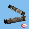
Cisco switch 10G SFP LR
10Gb/s 1310nm Single-mode SFP+ Transceiver XSFP-SM1310-10G-10KM
PRODUCT FEATURES10Gb/s serial optical interface compliant to 802.3ae 10GBASE-LR1310nm DFB transmitter, PIN photo-detectorDuplex LC connectorMetal enclosure, for lower EMIElectrical interface compliant to SFF-8431 specifications for 10 Gigabit 'SFP+'
2-wire interface for management specifications compliant with SFF 8472Single 3.3V power supplyOperating temperature range; -5°C to 70°C
APPLICATIONS10GBASE-LR/LW 10G EthernetPRODUCT SELECTIONXSFP-SM1310-10G-10KM
Notes1. Connected directly to TX data input pins. AC coupled thereafter.2. Or open circuit.3. Into 100 ohms differential termination.4. 20 – 80% Measured with Module Compliance Test Board and OMA test pattern.5. Loss Of Signal is LVTTL. Logic 0 indicates normal operation; logic 1 indicates no signal detected.6. Receiver sensitivity is compliant with power supply sinusoidal modulation of 20 Hz to 1.5 MHz up to specifiedvalue applied through the recommended power supply filtering network
Notes1. Circuit ground is internally isolated from chassis ground.2. TFAULT is an open collector/drain output, which should be pulled up with a 4.7k – 10k Ohms resistor on the hostboard if intended for use. Pull up voltage should be between 2.0V to Vcc + 0.3V. A high output indicates atransmitter fault caused by either the TX bias current or the TX output power exceeding the preset alarmthresholds. A low output indicates normal operation. In the low state, the output is pulled to <0.8V.3. Laser output disabled on TDIS >2.0V or open, enabled on TDIS <0.8V.4. Should be pulled up with 4.7kΩ- 10kΩ host board to a voltage between 2.0V and 3.6V. MOD_ABS pulls line
low to indicate module is plugged in.5. Transceiver data rate selected through the 2-wire bus in accordance with SFF-8472 Rev. 10.5. Soft RS0 is set atBit3, Byte 110, Address A2h. Soft RS0 default state on power up is ‘0’ LOW, and the state is reset following apower cycle. Writing ‘1’ HIGH selects max data rate operation. Transceiver data rate is the logic OR of theinput state of the RS0 pin and soft RS0 bit. Thus, if either the RS0 pin OR the soft RS0 bit is HIGH then theselected data rate will be 9.95 and 10.3 Gb/s.6. Loss of Signal is LVTTL. It should be pulled up with 4.7kΩ – 10kΩ on host board to a voltage between 2.0V and3.6V. Logic 0 indicates normal operation; logic 1 indicates loss of signal.Pin out of Connector Block on Host BoardDigital Diagnostic
Cisco switch 10G SFP LR

